产品详细说明:
| | |
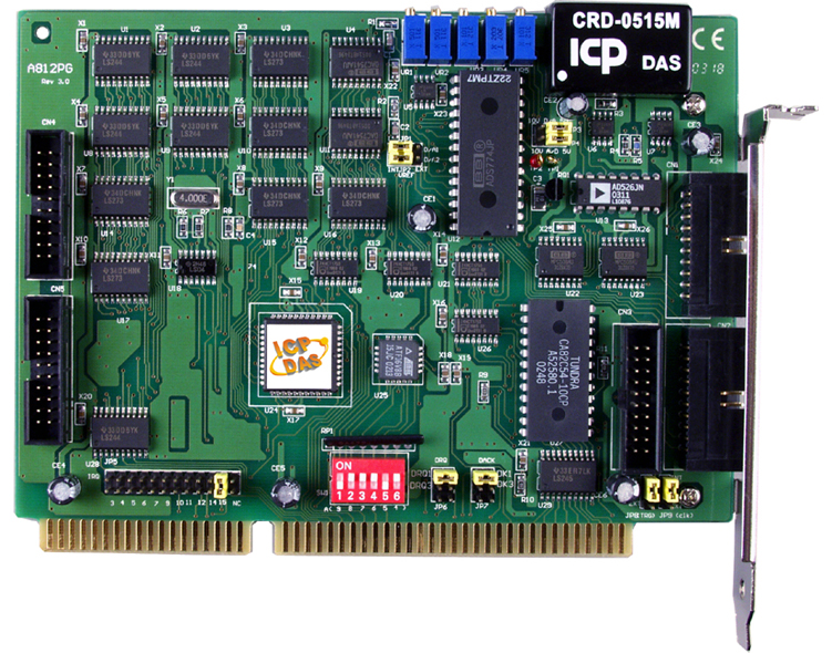
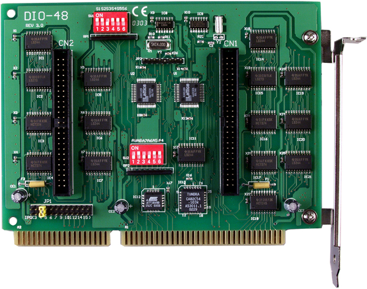
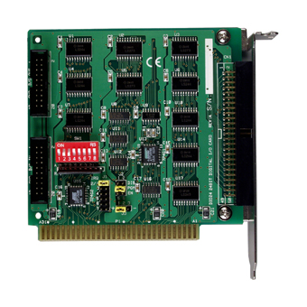
| | The DIO-24 provides 24 TTL digital I/O lines. The DIO-24 emulates 8255 mode 0 and has an increased output current of 15 mA (source) and 64 mA (sink) , allowing it to control LED, relay, etc. The DIO-24 consists of three 8 bit bi-directional ports and 2 input lines for interrupt enable and interrupt. The 8 bit ports are named port A(PA),port B(PB) and port C(PC). The port C can be split into two four bit. All ports are configured as inputs upon power-up or reset. The DIO-24 uses 4 consecutive I/O locations in I/O addressing space. The base address is selectable from 200 to 3FF hex. The interrupt signal can be connected to any of the interrupt levels 2 through 7 . |
| |
| back | |
| | |
| | |
| | |
| - 24 digital I/O lines
- Emulate 8255 mode 0 (Basic Input / Output mode)
- Buffer output for higher driving capability than 8255
- Register compatible to 724 series
- Programmable interrupt handling
- Output status readback
|
| |
| back | |
| | |
| | |
| | |
| ·Factory automation ·Product test ·Test automation
| |
| |
| back | |
| | |
| | |
| | |
| ·DOS sample program(with source codes) ·DLL and OCX SDK for Windows 98/NT/2000 ·DLL and OCX SDK for 32-bit Windows XP/2003/Vista/7 ·VB/VC/Delphi/BCB sample programs with source codes are included ·LabVIEW toolkit for Windows ·Driver for Linux and DasyLab
|
| |
| back | |
| | |
| | |
| | |
| | Digital Input | | Channels | 24 (OPTO-22 compatible) | | Compatibility | 5 V/TTL | | Input Voltage | Logic 0: 0.8 V max.Logic 1: 2.0 V min. | | Response Speed | 1.0 MHz (Typical) | | Digital Output | | Channels | 24 (OPTO-22 compatible) | | Compatibility | 5 V/TTL | | Output Voltage | Logic 0: 0.4 V max.Logic 1: 2.4 V min. | | Output Capability | Sink: 0.8 mA @ 0.8 VSource: -2.4 mA @ 2.0 V | | Response Speed | 1.0 MHz (Typical) | | General | | Bus Type | ISA | | I/O Connector | 20-pin box header x 250-pin box header x 1 | | Dimensions (L x W x D) | 182 mm x 110 mm x 22 mm | | Power Consumption | 900 mA @ +5 V | | Operating Temperature | 0 ~ 60 °C | | Storage Temperature | -20 ~ 70 °C | | Humidity | 5 ~ 85% RH, non-condensing |
|
|
|
| |
| back | |
| | |
| | |
| | |
| | DIO-24 CR | 24-channel Digital I/O Board (RoHS) |
|
|
| |
| back | |
| | |
| | |
| | |
| | CA-2010 | 20-pin flat cable,1 M | | CA-2020 | 20-pin flat cable 2 M. | | CA-5002 | 50-pin flat cable 20 cm | | CA-5015 | 50-pin flat cable 1.5 M | | DB-24P | 24-channel Photo Couple Isolated Digital Input Daughter Board | | DB-24R | 24-channel Relay Output Daughter Board | | DB-24C | 24-channel Open Collector Output Daughter Board | | DB-16P8R | 16-channel Isolated Digital Input And 8-channel Relay Output Daughter Board | | DB-24POR | 24-channel Photo Mos Relay Output Daughter Board | | DB-24PR | 24-channel Power Relay Output Daughter Board |
| |
| | |
| | |
| back | |
| | |
| | |
| | |
| |
The DIO-24 provides 24 TTL digital I/O lines. The DIO-24 emulates 8255 mode 0 and has an increased output current of 15 mA (source) and 64 mA (sink) , allowing it to control LED, relay, etc. The DIO-24 consists of three 8 bit bi-directional ports and 2 input lines for interrupt enable and interrupt. The 8 bit ports are named port A(PA),port B(PB) and port C(PC). The port C can be split into two four bit. All ports are configured as inputs upon power-up or reset. The DIO-24 uses 4 consecutive I/O locations in I/O addressing space. The base address is selectable from 200 to 3FF hex. The interrupt signal can be connected to any of the interrupt levels 2 through 7 . back •24 digital I/O lines •Emulate 8255 mode 0 (Basic Input / Output mode) •Buffer output for higher driving capability than 8255 •Register compatible to 724 series •Programmable interrupt handling •Output status readback back •Factory automation •Product test •Test automation•Digital I/O control •Alarm monitoring •4-channel SSR Output Daughter Board back •DOS sample program(with source codes) •DLL and OCX SDK for Windows 98/NT/2000 •DLL and OCX SDK for 32-bit Windows XP/2003/Vista/7 •VB/VC/Delphi/BCB sample programs with source codes are included •LabVIEW toolkit for Windows •Driver for Linux and DasyLab back Digital Input Channels 24 (OPTO-22 compatible) Compatibility 5 V/TTL Input Voltage Logic 0: 0.8 V max.Logic 1: 2.0 V min. Response Speed 1.0 MHz (Typical) Digital Output Channels 24 (OPTO-22 compatible) Compatibility 5 V/TTL Output Voltage Logic 0: 0.4 V max.Logic 1: 2.4 V min. Output Capability Sink: 0.8 mA @ 0.8 VSource: -2.4 mA @ 2.0 V Response Speed 1.0 MHz (Typical) General Bus Type ISA I/O Connector 20-pin box header x 250-pin box header x 1 Dimensions (L x W x D) 182 mm x 110 mm x 22 mm Power Consumption 900 mA @ +5 V Operating Temperature 0 ~ 60 °C Storage Temperature -20 ~ 70 °C Humidity 5 ~ 85% RH, non-condensing back DIO-24 CR 24-channel Digital I/O Board (RoHS) back CA-2010 20-pin flat cable,1 M CA-2020 20-pin flat cable 2 M. CA-5002 50-pin flat cable 20 cm CA-5015 50-pin flat cable 1.5 M DB-24P 24-channel Photo Couple Isolated Digital Input Daughter Board DB-24R 24-channel Relay Output Daughter Board DB-24C 24-channel Open Collector Output Daughter Board DB-16P8R 16-channel Isolated Digital Input And 8-channel Relay Output Daughter Board DB-24POR 24-channel Photo Mos Relay Output Daughter Board DB-24PR 24-channel Power Relay Output Daughter Board back
I/O Card Main Page


 发布供求信息
 推广企业产品
 建立企业商铺
 在线洽谈生意