| |
A-628/S CR信息 |
 点击图片查看原图 |
|
|
|
|
|
产品详细说明
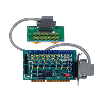
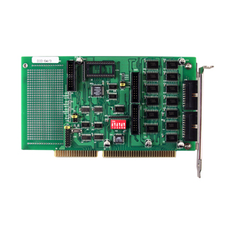
产品详细说明: | | | | The A-626,A-628 are 12-bit analog output boards with 16 channel digital input and 16 channel digital output .The A-626,A-628 boards support both current and voltage range .The output channel can be jumper selectable for different voltage range ;+/-10 V, +/-5 V, 0 ~ 5 V, 0 ~ 10 V and can sink 4 ~ 20 mA current when connected to an external voltage source. On board reference chip BB Ref-01 is used for solving the thermo-drifting problem of the reference voltage Therefore A-626 is much better than 726 families for long period operation. Lattice FPGA on board can increase the stability of the board. |
| | | back | | | | | | | | | | | | - Backward compatible to 726 series
- 6 or 8 analog output channels
- 12-bit resolution
- 0 ~ 5 V,0 ~ 10 V,*5 V,*10 V output range
- 4 ~ 20 mA current loop capability ,sink to ground
- On board reference -5 V, -10 V
- External reference *10 V (max.) AC or DC
- External Interrupt request signals, IRQ level from IRQ 3 ~ IRQ 15
- 16-channel digital input and 16 channel digital output Connects directly to DB-16P,DB-16R DN-20,DN-37, 782 and 785 families
|
| | | back | | | | | | | | | | | | ·Signal analysis ·Industrial automation ·Laboratory automation ·Sensor interface
| |
| | | back | | | | | | | | | | | | ·DOS sample program(with source codes) ·DLL and OCX SDK for Windows 98/NT/2000 ·DLL and OCX SDK for 32-bit Windows XP/2003/Vista/7 ·VB/VC/Delphi/BCB sample programs with source codes are included ·LabVIEW toolkit for Windows ·Driver for Linux and DasyLab
|
| | | back | | | | | | | | | | | | | Model Name | A-626 | A-628 | | Analog Output | | Channels | 6 | 8 | | Resolution | 12-bit | | Accuracy | 0.01% of FSR ± 1 LSB @ 25 °C, ± 10 V | | Output Range | Unipolar: 0 ~ 5 V, 0 ~ 10 VBipolar:+/- 5 V, +/- 10 V | | Output Driving | +/- 5 mA | | Slew Rate | 0.6 V/μs | | Output Impedance | 0.1 Ω max. | | Operating Mode | Software | | Digital Input | | Channels | 16 | | Compatibility | 5 V/TTL | | Input Voltage | Logic 0: 0.8 V max.Logic 1: 2.0 V min. | | Response Speed | 1.0 MHz (Typical) | | Digital Output | | Channels | 16 | | Compatibility | 5 V/TTL | | Output Voltage | Logic 0: 0.4 V max.Logic 1: 2.4 V min. | | Output Capability | Sink: 0.8 mA @ 0.8 VSource: -2.4 mA @ 2.0 V | | Response Speed | 1.0 MHz (Typical) | | General | | Bus Type | ISA | | I/O Connector | Female DB37 x 120-pin box header x 2 | | Dimensions (L x W x D) | 157 mm x 106 mm x 22 mm | | Power Consumption | 0.9 A @ +5 V (Max.)110 mA @ +12 V (Max.)90 mA @ -12 V (Max.) | 1.1 A @ +5 V (Max.)130 mA @ +12 V (Max.)105 mA @ -12 V (Max.) | | Operating Temperature | 0 ~ 60 °C | | Storage Temperature | -20 ~ 70 °C | | Humidity | 5 ~ 85% RH, non-condensing |
|
|
|
| | | back | | | | | | | | | | | | | A-626 CR | 6-channel 12-bit Analog Output and Digital I/O Board (RoHS)Includes one CA-4002 D-Sub connector. | | A-626/S | A-626 + DB-37 | | A-628 | 8-channel 12-bit Analog Output and Digital I/O BoardIncludes one CA-4002 D-Sub connector. | | A-628/S | A-628 + DB-37 |
|
|
| | | back | | | | | | | | | | | | | CA-2010 | 20-pin flat cable,1 M | | CA-2020 | 20-pin flat cable 2 M. | | CA-3710 | DB-37 Male-Male D-sub cable 1 M (Cable for Daughter Board(45°)) | | CA-3710D | DB-37 Male-Male D-sub cable 1M (Cable for Daughter Board(180°)) | | CA-3710DM | DB-37 Male-Male Cable, 1.0 M, 180°. (RoHS) | | CA-3730DM | DB-37 Male-Male Cable, 3.0 M, 180°. (RoHS) | | CA-3750DM | DB-37 Male-Male Cable, 5.0 M, 180°. (RoHS) | | CA-4002 | 37-pin Male D-sub connector with plastic cover. | | DB-37 | Directly connect signal to D-sub 37-pin connector | | DN-37 | DIN Rail Mounting 37-pin Connector | | DB-16P | 16-channel Isolated Digital Input Daughter Board | | DB-16R | 16-channel Relay Output Daughter Board | | DN-20 | I/O Connector Block with DIN Rail Mounting and 20 -PIN Header |
|
|
| | | | | | | | | back | | | | | | |
|


 发布供求信息
 推广企业产品
 建立企业商铺
 在线洽谈生意